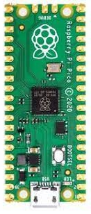
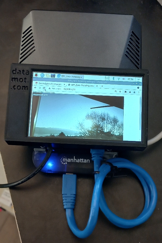
This Blog lists some key insights I gained on Arduino, ESP32-S3 (Lilygo), RP2040 and Raspberry Pi
ESP32-S3 WiFi connection stability / October 2023
I noticed that the ESP32S3 sometimes looses WiFi connectivity, which is not reflected in WiFi.status(). My workaround is to check every 15 seconds, whether I can make a connection to port 80 of the gateway, and when not successful reset WiFi:
[ .. Code snippet .. ]
//check TCP connectivity -- Here, this piece of code is executed once per second
if (seconds%15==0){ //every 15 seconds check ('seconds' is part of my clock)
WiFiClient client2; //make a new client (executed every 15 seconds)
IPAddress myGW=WiFi.gatewayIP(); //create ip address of the gateway
if (client2.connect(myGW, 80)) { //make a connection to the gateway, typically the router, which has http management (port 80)
GWgood++; //increment my good test counter
} else {
GWbad++; /increment the bad test counter
WiFi.reconnect(); //force a reconnect
}
client2.stop(); // no longer needed, close the client
}
After testing for a few days, this has proven to work reliably. I did not observe a change in WiFi.status(), nor did setting core debug level to verbose show any useful information in the Serial Console.
I suspect the above is a bug of some sorts, that a few people ran into. My above workaround does not take much resource in terms of code, memory or CPU time.
ESP32-S3 by Lilygo Battery Power / August 2023
The Lilygo ESP32-S3 T-Display is a great part, but documentation is hard to find. It took me a while to figure out the following:
If only Battery powered, the ESP32-S3 actually is powered and runs. However, unless the user (I use the Arduino IDE) sets GPIO 15 HIGH, the LCD is not powered, neither the green LED nor the R-divider network that let's you check the voltage on GPIO 4.
If you reset the module, only using battery power, the LCD controller has no power and is not initialized, hence it will not display anything when you later connect USB power. In summary:
The PWR_EN (GPIO 15) pin controls:
-The green LED
-The LCD power
-the input to the Resistor divider network that lets you analogRead() a corresponding power supply value
Moreover, supplying USB power is having the same effect as setting PWR_EN HIGH.
What is confusing: when USB power is supplied the BAT_ADC net (to GPIO 4) acually measures the USB supply and not the BATtery voltage. I think turning off the R-divider input on battery power makes no sense, perhaps it will be corrected in a future version (ref: Schematics 3/13/2023).
The part has an integrated 3V3 voltage regulator for the ESP32, and a LiPo charge chip to charge a LiPo when connected to USB power. That chip gets really hot.
I think the user sketch has to check whether the lower battery voltage has been reached, and then put GPIO 15 low, and put the ESP32 in deep sleep. If your user sketch does not do this, you run the risk of killing the LiPo battery (due to undervoltage).
RPi-4 USB3 power supply problems / February 2022
I have not found much about this issue on the Internet.
The problem is that when connecting a USB3 - SATA adapter with an SSD drive to RPi-4 to get good rootfs performance, not enough power is supplied to the USB port and the drive goes erratic and the OS crashes. I tried various USB3 SATA adapters and various OSs (I prefer Fedora). After many months of elapsed time, I figured out that the FET powerswitch on the RPi4 that enables power on USB (I do not understand why it is designed this way) is too weak. The remedy is simple: I solder a wire directly from the 5V pad at the USB power connector to the USB connector pin that supplies the 5V to USB. The system now runs stably for months! I have not noticed negative side effects. Comments: please email me at ronald (dot) gadget (at) gmail.com
Arduino & Feather RP2040 + Earle Philhower: HowTo and Learnings / 22 Dec 2021
I spent two weeks learning how to get [Arduino & Feather RP2040 & Earle Philhower's core] working, migrating my sketch from a nano Every... In the process, I declared the hardware as 'bad' and almost gave up on this part at least 3 times. However, the hw is great - it is a matter of understanding how the part behaves, partially correct documentation and being among the first ones to use this. I tried using the VSCode IDE, but gave up as PlatformIO does not yet officially support Philhowers board package (mid december 2021).

- When the code crashes, the Serial Port is gone! This implies you have to use the bootsel button to get the drive port back - but then the Arduino IDE cannot load the new FW. I then first load the circuit python UF2 file to get the port back. Yikes. And, the RP2040 is much quicker to crash than a Nano. The RP2040 is much less forgiving with sloppy code than classical arduinos...
- An INT is not an INT. On the Nano, the INT is 16 bits, on the RP2040 it is 32 bits. When converting an INT to a string, the result can produce very long strings, and exceed the allocated char array size (using itoa() ). On the Nano, given small amount of RAM I had the char[.] at smallest required sizes. I migrated the code to RP2040 and exceeded the string length due to unexpected INT values. This crashed the code (see 1.). Furthermore, some of my INTs are dynamically allocated (malloc()) so the values survive a reset (I use these INTs for time and date). This lead to a situation that crashed the RP2040 with a power cycle (not on a reset cycle!), and convinced me at first that the flash gets corrupted on a power cycle. When reflashing, the code did not crash, as loading the new fw zeroed out the dynamic INTs. However, it was my sloppy code: flash is not corrupted (it was my brain...!). This took me 3 days to find out.
- Using the second core with loop1(): I only got this to work using Philhowers setup. Not in stock arduino.
- No default pins on spi1. I need both spi ports as the SD library and CC1101 libraries bite each other on the RP2040 (Not on the Nano!). Using Philhowers setup, I was able to modify the CC1101 library to use spi1(). However the .setRX() etc methods did not work. I ended up setting the RP2040 configuration registers directly to solve that issue. That works: however do it before SPI1.begin(). That took me 3 days to get working. See the RP2040 datasheet from RaspberryPi.
- Setting SPI speed with .beginTransaction() does not work. Again, I access the registers directly. See the RP2040 datasheet from RaspberryPi.
22 Dec 2021 (I may add further points in future).
Notes: I wanted to buy the Raspberry Pico, but shipping costs were 3 times the part costs (don't know what they were smoking). So I ordered the adafruit part thru digikey with reasonable shipping costs. The Arduino RP2040 connect has wifi+bt that I dont need and want to pay for. And too high shipping costs.
Philhower docu:
Installing the Earle Philhower core | Program RP2040 in Arduino | Adafruit Learning System
RPi4 + Argon One case + Hyperpixel 4 display: fan control not working / January 2022
 The Pimironi Hyperpixel display uses all GPIO pins on the header. Obviously, the Argon One also uses some pins, which yields a conflict. This results in the FAN control not working (based on temperature). The main issue is the i2c pins, which the display does not configure as i2c. I found this out by going thru the dmesg output right after boot, where a message informs about this conflict. Of course, you have to actively go an look for this. The good news is that the Hyperpixel display provides.... an i2c connector! Thus I solved the problem by cutting the circuit board i2 traces to the Argon One chip that controls the fan speed, on the Argon One circuit board that connects the RPI4 GPIO connector to the Argon One GPIO connector. The last step is to adapt the python script that is run as a service to use the new i2c interface (thru this error message I discovered how to fix the issue). The system now works as desired!
Data Motion Architecture & Consulting GmbH - Ronald's pagecounter
3920
page visits since 6 March 2022

 The Pimironi Hyperpixel display uses all GPIO pins on the header. Obviously, the Argon One also uses some pins, which yields a conflict. This results in the FAN control not working (based on temperature). The main issue is the i2c pins, which the display does not configure as i2c. I found this out by going thru the dmesg output right after boot, where a message informs about this conflict. Of course, you have to actively go an look for this. The good news is that the Hyperpixel display provides.... an i2c connector! Thus I solved the problem by cutting the circuit board i2 traces to the Argon One chip that controls the fan speed, on the Argon One circuit board that connects the RPI4 GPIO connector to the Argon One GPIO connector. The last step is to adapt the python script that is run as a service to use the new i2c interface (thru this error message I discovered how to fix the issue). The system now works as desired!